524x530 Working area build log

I’m starting this as a build log to help other builders, ask for help and maybe integrate my material into the official build guide from the wiki (there are some missing steps).
Here are some specs of my planned build:

Working area: 524x530mm
Box section length: All 660mm
Box section material: 20x20x2 stainless steel
Spindle: Planned for Air cooled 1.5Kw spindle from G-penny like suggested on the discord.
Steppers: 59Ncm 2A from Stepperonline from the BOM
Stepper drivers: DM332T from Stepperonline
Controller: Root controller 2.1
Printed parts: Printed with a 0.6 nozzle with Blue, Black, and Clear PETG, 50% infill, 3 perimeters (0.6 perimeters are thicker than 0.4 perimeters)

I’ll try to make a “standard” build following the project, then maybe there will be tweaks if I want to improve.

I ordered most of the components from aliexpress, so the build will be done in my spare time using the parts I received.

I live in an apartment, so space is gold, and I have to try to get it portable, so I can put it outside my balcony for the dustier projects.

This is built on spare time, in an apartment, with family, sport and work having precedence, so don’t expect a fast build schedule!

General random tips:

  • Get your screws as soon as possible! everything is held together with screws, so If you don’t have them you can’t proceed assembling in any way. And also you’ll know as soon as possible if you got some wrong ones. I prefer (especially for a vibration-subject build like this) using lock nuts when possible, so you’ll probably find more than the ones counted in the official BOM. Ordering them from aliexpress is pretty cheap, they cost a bit less than the normal ones but will save you from problems with retightening loose screws.
1 Like

Printing:
I printed everything in PETG on a 190x200 build plate. Even the biggest parts are printable on a “standard” 200x200 print bed.
Used my custom built i3 rework boxed, so you’ll not need an expensive printer.

I used an original e3d 0.6 mm nozzle as I used it for the last months, it should have better strength over a 0.4 one, a 0.35 layer height is well within its range. This helps to have thicker perimeters and print with 3 perimeters instead of 4, saving print time.
I used various colors, mainly as I used the blue roll I had opened, then used an entire roll of black, and then ended with some clear I had. I’m definitely not strict on building with a nice color scheme, it has to work, if I can do something to make it pretty I do it, but I don’t strive for aestetics, So I even have some bicolor parts when the filament ran out!


Some parts need to be printed with supports, I used the “paint support” of Prusa Slicer to put them only where needed, took some screenshots and I’ll push them to the “How to print” page on the wiki, so you can check there.

It took some weeks to print all the parts without printing overnight, printing almost always 1 part at a time and without printing all day long every day. I started printing while waiting for the aliexpress orders to arrive, so I wasn’t in a hurry.

1 Like

Carriages
I started assembling some carriages I only got 10 bearings (orders are still in transit), and only 10 M5x50 (the seller sent 10 instead of 20, so the others are on the way).

Unfortunately, I ordered the wrong M5x20 screws, so I can’t build as stated in the build guide, but I found a good workaround that can be even easier!
I put the lock nut inside the recess, and the head of the screw outside:


1 Like

Cost Breakdown:
This question is asked frequently on the discord group. Every build is different, so I made a Google sheets with my build:

Z Linear Rails
The assembly of the z linear rails is pretty easy, you should orientate them so the upper end is flush to the bearing block, or at least not sticking out to be able to mount the bearing block afterwards.
Here I used 10 M3x14 screws (the black ones), and 2 M3x10 screws (the others). the M3x10 are on the holes that are aligned with the x axis bearing block mount holes, as with longer screws you’ll not be able to fit the bearing screws later. You can probably use all M3x10 screws, but I have a bag of the 14mm ones left over from my 3Dprinter build so I used them.
Everything is held in place with locknuts (I don’t know if the original project uses locknuts here but I’ll use them when possible!
Remember that now the carriages are not blocked and you should never get them out of the rail, so I left the orange caps to avoid them sliding out. Also, I didn’t yet add the additional carriages, so if everything goes bad I break only one or two and not all 4.

Y box mount (front side)
While waiting for other parts I kept assembling what I had, so I prepared the front Y box mounts.
Parts used:
2x Y_Axis_BoxMount printed parts
2x Y_Axis_Idler
12x M3x14 screws (used these as I had a lot of them and are a little longer than needed
12x M3x9 washers
12x M3 Locknuts
2x 608RS sealed bearings
I also prepared the feet using:
2x Y_Axis_Foot
8x M3x30 screws (Length from the build video, which uses pan head, I used cap head, but maybe I’ll change them before final assembly)
8x M3 nuts (the normal ones, as the lock ones don’t fit in the hole.
8x M3x9 washers

The pictures should be pretty self-explanatory.
The bearing goes on the side of the hole for the box mount, and should go inside without too much pressure. If it’s too tight gently sand the hole and try again.
the washers are only on the screw head side, as the nuts have their hexagonal recess to block them.
Obviously, the M3x30 screws are there only temporarily, as you’ll need to remove them to mount the parts to the base.

Y motors to motor mounts
Parts used:
2x Y_Axis_Motor_FK10_BearingMount
2x 5 to 8mm couplers
2x stepper motors
8x M3x10 cap head screws (M3x14 are too long, so 10 should be the right length)
8x M3x9 washers

You can mount the couplers to the shaft before mounting the motor to the mount, so it’s easier to lock the screw.
Keep particular attention to the orientation of the motor mount. There are two protrusions to align it to the Y box mount, but they’re not centered. I had to view the video several times to catch the correct orientation, you can see it better in the following picture (they should be far from the motor).
Also, use the protrusions to choose where you want the motor’s cables to exit. I mounted both with cables going downwards.

Spindle clamp screws
Another little step you can make having only fixings and the printed parts is assembling the spindle clamp screws.
Parts needed:
1x Z_Axis_Carriage_65mm
4x M3x20 screws (pan or cap head should make no difference, you’ll find pan head in the pictures, but I can change them as cap head could be easier to fasten with a bigger hex key) the 25mm screws seem to be too long, so 20 should be the right size.
4x M3x9 washers
4x M3 locknuts (the original project uses normal nuts, but these are at the source of vibrations, so why not locknuts?)

Just assemble Screw → washer → clamp → locknut like in the pictures.
You’ll also see the screws for the z axis ballscrew nut attached, but I’m not sure about the screws type/length, so we’ll talk about them later.

Cutting the box sections
As stated in the description I used 20x20x2 stainless steel box sections.
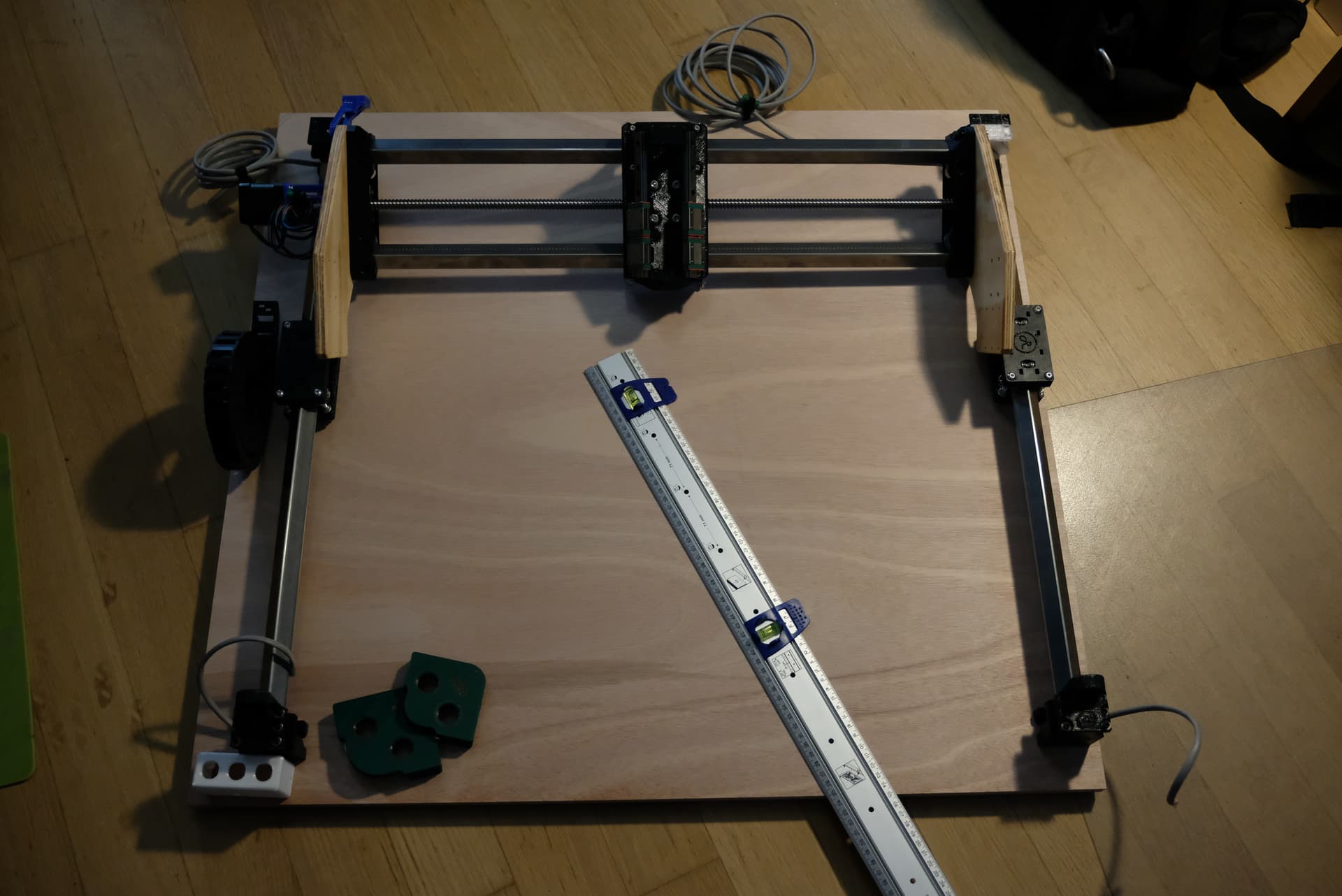
From the build area calculator, I needed 4 660mm pieces.
Warning:
In the following steps you’ll see me cutting 4 660mm pieces, but that’s a “scalable” measure, and in most cases you’ll have 2 pieces of one length and 2 of another, having them the same size is only a particular case of my build. If you have two different sizes just work with two at a time instead of 4.

Parts needed:
box sections - I ordered a 2m long and a 1m long, so I had to cut 1 660mm piece from the 1m bar and 3 from the 2m one.

The long story of working with stainless steel begins:
The original project uses aluminum, but uses 360mm and 410mm pieces. I wanted a bigger build, so I scaled up, and so came the fear of aluminum flexing too much. I asked in the discord, someone I can’t remember said he had a bit of wobble on the x axis with aluminum on a bigger than standard build. After checking online stores selling both 20x20x2 alu and stainless steel, the difference was around 20 Euro shipping included. I concluded that when spending hundreds of euros on building a machine, realizing that it wobbles because I wanted to save 20 Euro was not a scenario I wanted to find myself on, so I ordered 20x20x2 stainless steel bars. And then started the long story of working with stainless steel!!

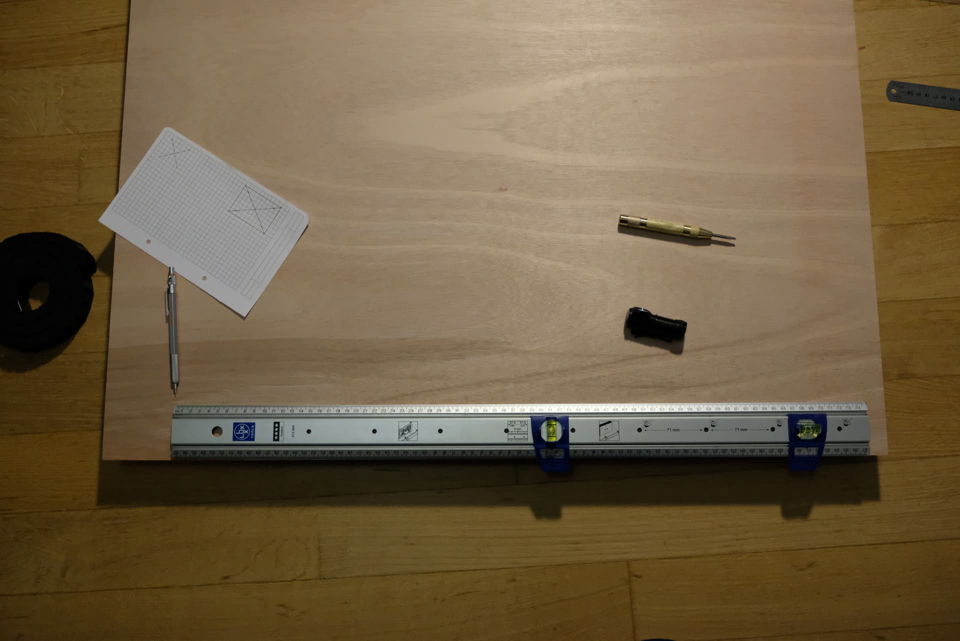
The first tip you should remember if you have a long bar to cut in pieces is that you shouldn’t measure all the cutting points, mark them, and then cut everything. Measure the length from the tip, mark, cut (better longer than shorter), measure, mark, cut…
Remember that cutting removes some length. I selected 660mm as with 660x3 I had 1980mm, so I had 20mm for the blade’s kerf and to cut a little longer and refine afterwards.

I started with a manual saw as I previously worked with aluminum profiles, and I thought it should be easier to get a good straight cut… But stainless steel is not aluminum, and that’s why I went with it: it’s very hard! So yes, I tried the manual way, and I recommend it for aluminum builds.

After an hour or so of sawing I realized that It was too hard to cut, so I got out my angle grinder, loaded a cutting disk and started cutting. I cut everything a couple mm longer than 660 to be able to refine the cuts and get everything the right length after.


After I cut everything a bit longer, I removed some imperfections from the edges with a “cleaning fleece for removing dust and paint”. Probably not the best disk for the job, but I just needed to have clean edges to use to align the pieces.

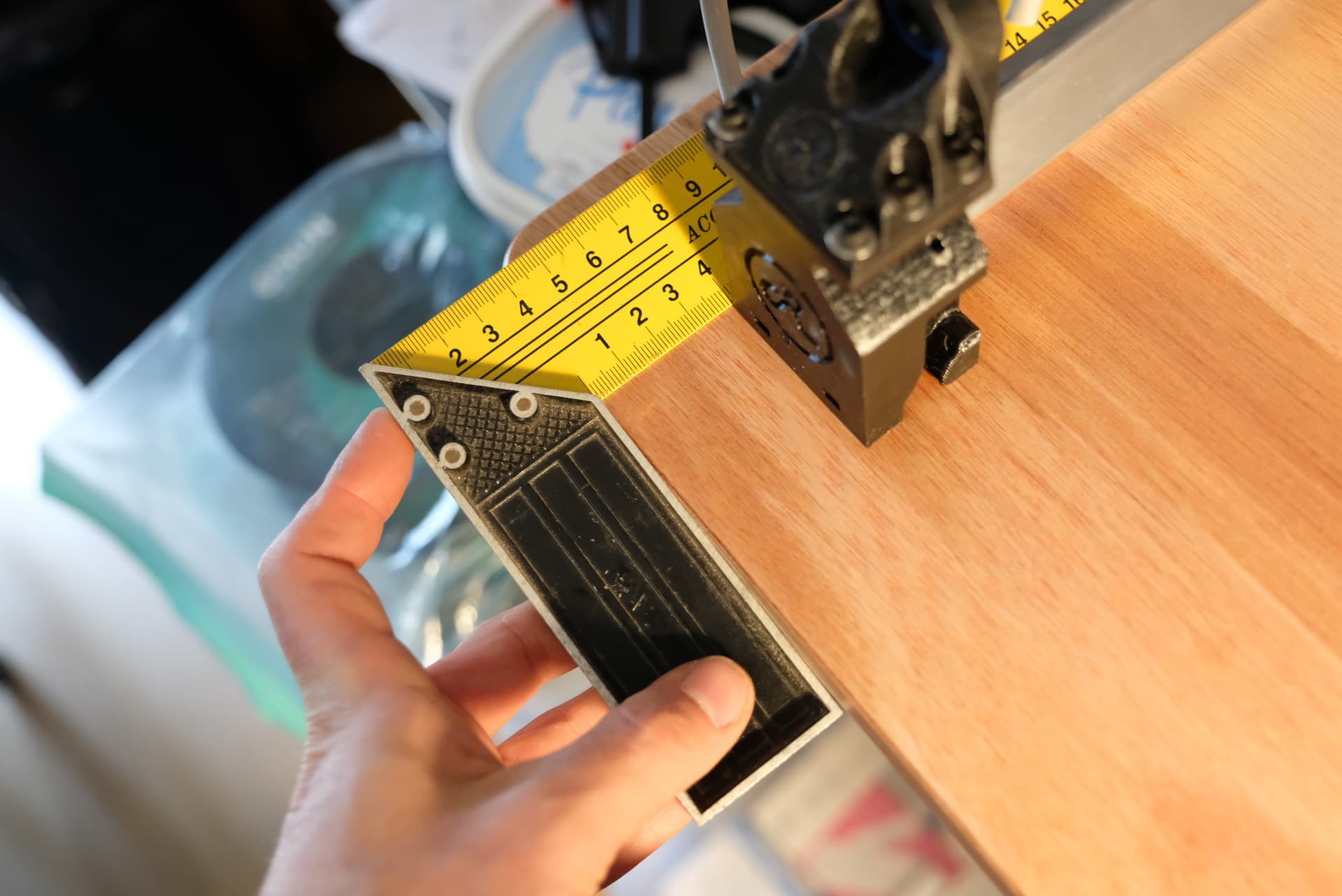
Then I aligned the box sections two by two using a square to get one end aligned.


Then I joined the four sections aligning them on the same side. (remember that you should not need to process the four sections together)

Next I clamped the four sections on the side I used to align and used an abrasive disk to get them all equal and square

I used the square to check for squareness

If you’re using aluminum it should be easy to do using a file or a sanding block.
you can use a marker to mark the edge

then you sand and look where the marker is removed and where not to Identify high and low spots.

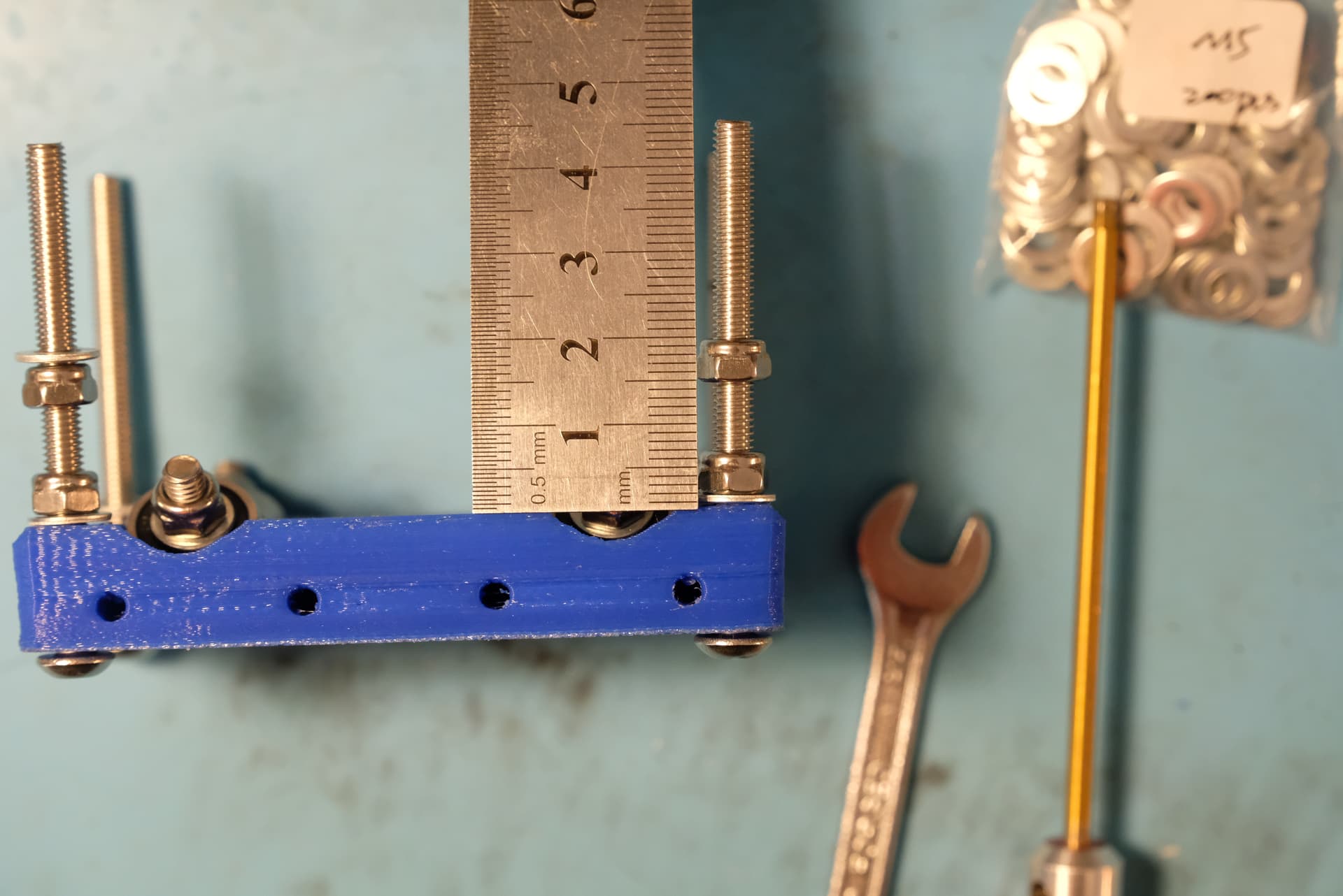
When the first side is done you can measure again using the edge you just squared as a reference.
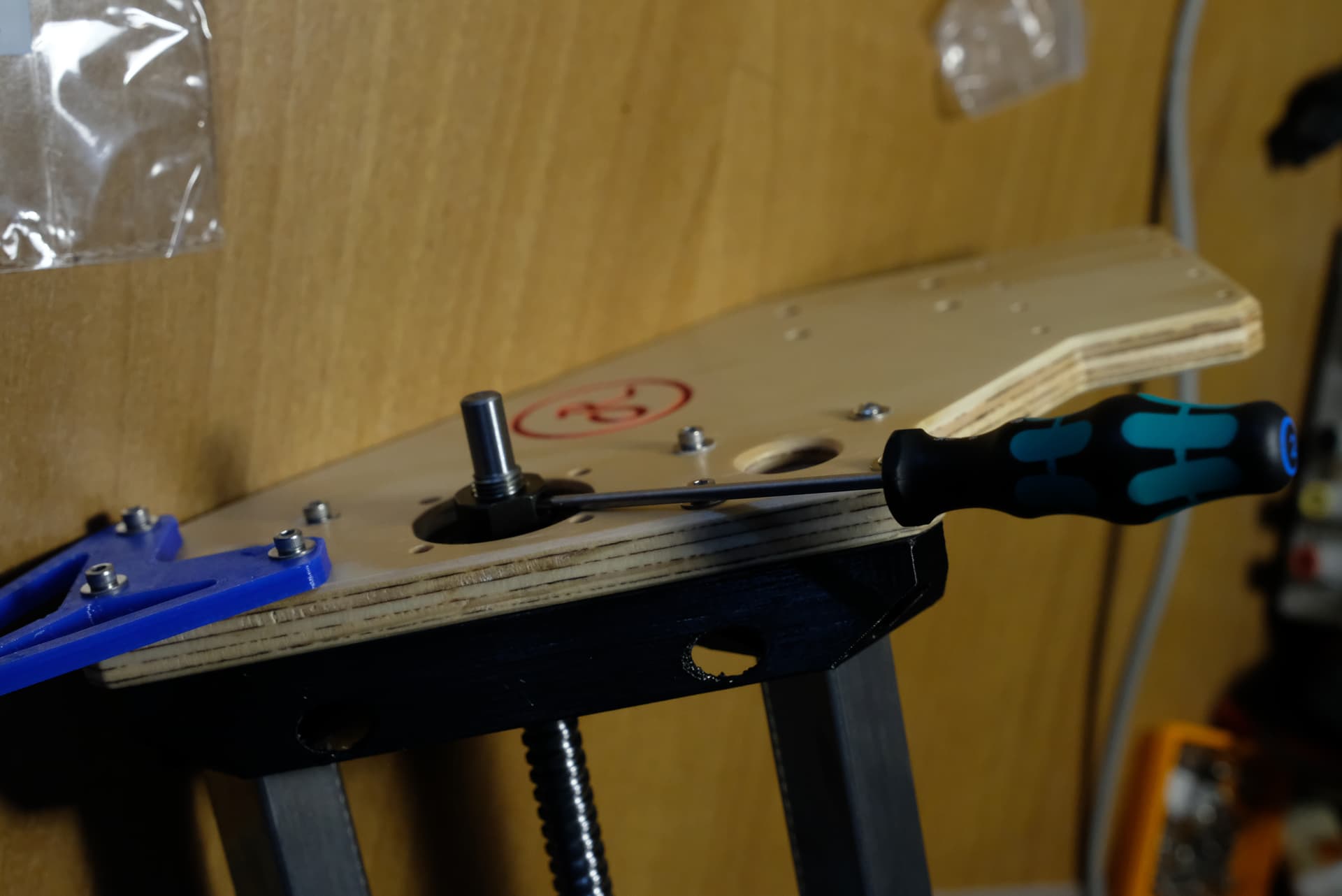
I used the square and a cutter to mark the steel with a precise, little, but durable mark all around the boxes to have a reference on all sides.

Then I clamped everything back vertically on the table (this time the other way up)

Then it’s only a matter of cutting, grinding, filing, whatever you need to get everything square and aligned with the cutter mark.

grinding everything perfectly square is pretty difficult with stainless steel, but in the end I got a good result, the length is almost perfectly what I needed.

In the end I smoothed the external edges with the “softer” disk and the inside ones with a file.

Final notes
I put a lot of effort on getting the length just right, probably more than needed, but I enjoy the process of building, I like trying to do it right, and anyway I didn’t have all the other parts, so I had time before I could go on with the build.
You can get by with way less precision, as long as you check that the box mounts align to the same length, but that’s how I enjoyed doing it, so I told you my experience!

After all this process I thought that it would be good to smooth and polish a bit the surfaces to help the bearings, so I sanded everything up to 1200 grit… but that’s out of the requirements of a normal build, maybe it’s even overkill and not completely worth it, so I’ll not detail that process.

1 Like

X and Y Carriages - step by step assembly
I already posted about the carriages, but it was not a step-by-step assembly, so here I am again assembling all 4 carriages.
Parts needed
8 X_Y_Axis_Carriage
32 625RS sealed bearings
32 M5x20 hex head screws
32 M5x60 pan head screws
64 M5 locknuts (the original project uses some non lock ones, but these coming loose is a known issue even on the root4, so now I think it’s recommended to use all locknuts)
80 M5x10 washers

It’s a lot of stuff, and a lot of work, you’ll screw many locknuts, that are not as easy as the normal ones, so you’ll need some tools.

The hex screwdriver ( the red tool on the right is a great tool, I have 4 of them, you can find many cheap sets from china, and I recommend buying them, I have the most common set with 1.5, 2, 2,5, and 3mm.) is a great help in this step, and on all the build, I think they’re worth it even if you buy them only for this build, as you’ll be able to use them on probably all the screws of the entire build.

I’ll show you how to build a single carriage, but probably the best way to build them is all together, making every single step on every carriage before proceeding. Making every step with a bit of concentration on all the pieces should avoid you to get in the “I forgot to put a washer under that bearing, so now I have to unscrew everything” situation.

Let’s get started.

  • Put the M5x20 hex head in the carriage and push it down until it’s fully inserted

  • Put an M5x10 washer on the M5x20 screw (step 1 in the picture)

  • Add a 625 bearing over the washer (step 2 in the picture)

  • Add another M5x10 washer over the bearing (step 3 in the picture)

  • Add and tighten an M5 locknut to lock everything in place (step 4 in the picture)

A little note… I bought cheap washers from china, I don’t know if other are better, but these have a “sharp” edges face, and a rounded edges face, probably derived from the cutting process during their production. You can easily identify them, in the previous picture for example the washer in number one has the rounded edges face facing above, while the one in step number 3 has the sharp face facing upwards. I realized late that if you put the sharp face side by side with the bearing, it could push against the bearing’s sealing (the black part) and introduce a bit of friction (not much, but once the locknut is tight you can feel the ones with that added friction to the ones without) so now that you know and you’re building, build it right, spend a couple of seconds and mount them the right way (with the rounded side facing the bearing, like in 1 and 3).
the top washer on step number 4 is probably an example of a washer put the wrong way (the rounded side is on the nut side)

Now that you built the base of all the carriages, you can start to join them.
Split the carriages in 4 sets of 2.
For one of every group follow the next steps

  • Put four M5x60 screw like in the picture (I didn’t use a washer between the screw’s head and the carriage as the head was already about 10mm in diameter, but maybe you can add one if you want)

  • Add an M5x10 washer (step 1 in the picture)

  • Add an M5 locknut and screw it down (don’t tighten it, you need it to be able to turn it to screw other locknuts on that screw, and it’s easier to turn the screw than turning the nut!) (step 2 in the picture)

  • Add another M5 locknut, this will be the blocking nut for the top half of the carriage, so you don’t need to screw it all the way down. (step 3 in the picture).

  • Add another M5x10 washer on top of the nut (step 4 in the picture).


    The locknuts make a lot of friction and so they can get hot in the 50mm you have to screw them down, so to avoid it you can rotate between the 4 nuts on each step, tightening a bit one, then another, then another and so on until all are done.
    here’s just a reference for how much space I left for the upper nut(don’t worry to get the exact number, you’ll have to move it after.

Now you can put the other half carriage, a washer, and a locknut.

Now you can tighten the first locknut, the one that locks against the screw head (step 2 in the assembly picture).

To get the two halves leveled I measured the distance with a caliper, and moved the nuts to get the same distance on all the 4 corners. It’s not important the number, it’s important to have the same number on all corners, you’ll refine the adjustment once you slide the carriage on the box section.

Once on the box section, I tightened the two upper nuts against each other, and then untightened the internal ones 1/4 of turn, tightened the external ones, and checked the contact between the bearings and the box section. You should continue tightening the carriage until all 8 bearings rotate at the same time, but there’s no excessive friction (you don’t need to push too much to move the carriage along the box section).

try to adjust every carriage in its final box section, so you adapt it to that particular piece.

X axis initial assembly
I still have to seal and paint the side panels, I’m waiting to buy the baseboard so I can get everything together, so this build will be partial, I’ll assembly the boxes to the mount, the carriages, and the z mount, then I’ll wait for the side panels to be ready.

Parts needed:
2 X_Axis_BoxMount
1 Z_Axis_MotorMount
1 Z_Y_Axis_BallscrewSpacer
1 Lead Screwball nut Housing/Mount SFU1204
2 box sections (the ones of the x-axis size)
1 Z_Axis_LinearRailMount (I already assembled the linear rails)
2 previously assembled carriages
24 M3 nuts (the normal ones, as the locknuts don’t fit in the holes of the carriages)
24 M3x7 washers
8 M3x14 screws (I used cap head)
8 M3x25 screws (I used cap head)
4 M3x20 screws pan head
4 M3x25 screws (I used pan head but cap head should be fine too)
4 M5x20 screws (I used cap head, hoping they will not interfer with the z axis carriage)
4 M5 washers

The first step (if you skipped when assembling the x/y carriages) is to insert a carriage in each of the box sections and adjust the screws to perfectly fit the carriage to the specific box section.
Then we can proceed with mounting the box sections to the x-axis box mount printed part.
These parts have an up and a down, so make sure to get the right orientation.
The end with the recess with two holes for the end-stop switches goes up.

Also, the carriages following the original build should have the long bolts pointing downwards (check the pictures).
The first step is inserting the box mounts into the holes in the first box mount and get them in until they’re flush with the panel side of the mount.

Here you can see the orientation of the carriages with the first mount assembled.

Then you can proceed with assembling the second mount (always check the orientation).
Once it’s mounted and the box sections are flush with the mount, you should check the distance between the mounts and make sure that the top and bottom are the same distance. This is why you should have the two box sections the right size and the same length between them.

Now I started assembling the z axis mount to the carriages.
I used the M3x25 cap head for the external holes as the bolt on the carriage is deeper, and the M3x14 cap head on the internal holes.
You should have something on hand to help you moving the nut into the carriage hole so the screw can grab on it and move it on its locking recess. (I used some metal carving tools I ordered from china and used for a lot of DIY tasks, you can see one of them in the pictures)

As you can see from the last picture, this is the right moment to get the additional z carriages into the linear rails.
To block them from escaping I just untightened the last screws of the mount, by moving them a little out, they get in the way blocking the carriages from escaping the rail. Just remember to tighten these screws later!

All these screws will be near the main source of vibrations, but we can’t use locknuts, so I used thread-locking liquid on the screws to hold them in place.
I wanted to be sure everything was fine before locking the screws, so I screwed everything, then I unscrewed a screw at a time, added thread lock, and screwed it again.
This is the result:

Next step I assembled the screwball nut housing.
Mine had M5 mounting threads, but the spacers I printed had M4 holes, so the screw didn’t fit.


I enlarged the holes with a 5mm drill and the screw finally got in.

When you mount the block to the x carriage, the orientation will determine on wich side the x motor will be. I’ll follow the original build and get it on the left side, so I mounted it with the threaded holes pointing to the left.
To mount it I used 4 M5x20 and 4 M5 washers. Also, I dropped some thread-locking fluid into the housing’s screw holes to lock everything in place. (hoping I’ll not need to change them with pan head screws later)
The assembly order is:
Screw → washer → z mount → spacer → ballscrew nut housing

Next I assembled the z motor mount.
After mounting the z rail mount it should be pretty intuitive, I just used pan head screws instead of cap head to get more space to move the motor to get the right tension on the belt on the final assembly.
M3x20 on the inside, and M3x25 on the outside.

The plate of the motor mount will go higher than the carriages, I initially thought it should be flat and asked myself what I did wrong… but after checking and re-checking on the build videos I found out that it’s normal!

And this is all for this session, now this piece will sit waiting for the side panels to be ready.

Side Panels

Parts needed:
2 Side panels

I ordered the side panels from the rootcnc store, so I got them already cut, drilled, and with a nice Root logo engraved.
They’re made of 12mm plywood and I decided to not color paint them to give some contrast between the stainless steel box sections and the wood.
This doesn’t mean I left them with bare plywood.
Firstly I used a router and a chamfer bit to put a little chamfer on the sides and inside the small holes for the Box sections (not the bigger central one, as it will have to strongly fit the bearings so I left there all the contact surface I could).
I don’t have pictures of that, but you can see the final effect on the following ones.
After the chamfer and a little sanding to remove the rough spots I applied two coats of wood sealer, with a light pass of sandpaper between them. (remember always to remove all the dust before painting with a brush, a vacuum cleaner, both, or whatever you prefer).
After the two coats, I put some tape around the engraved Rootcnc logo.


Then I made a hole in a piece of paper slightly bigger than the logo, and put it over the panel

Then I used an airbrush to paint the logo engraving red.

After everything dried, I removed the tape, and sanded the panel to remove all the red paint outside the engraving. The paint should not penetrate into the wood as you already sealed it with the clear sealer.
Then I took a small brush, some of the red paint, and added a bit more paint inside the logo.
This is the final result:

Then I airbrushed over two additional coats of clear matte finish to finish everything and “lock” the red paint between the two clear paints.
This is how I made it, now let’s see what you can learn from my mistakes:
First of all I want to clarify that painting the logo with a different color is only an aestetic step I wanted to try, it’s not required, and even Pete just painted in blue the whole panel and nothing more.
I think that the “airbrush everything and remove the paint from the flat part” can be a great solution for big and difficult engravings. This is just a little logo, maybe it could be easier to paint it directly with a small brush and sand the flat part to remove eventual mistakes.
If you don’t have an airbrush and want to use only brushes, remember to check that your coat doesn’t “melt” the color, or you’ll risk ruining your work.

Mounting side panels to the x gantry
Now that the side panels are ready, it’s time to mount them to the x gantry prepared earlier
Parts Needed:
1 X_Aixs_DragChainMount
2 side panels
12 M3x25 Cap head screws
4 M3x25 Pan head screws
16 M3x9 washers (BOM says penny washers, this is what I got, maybe you can find bigger ones)
16 M3 locknuts (BOM uses simple M3 nuts here, I’ll go with locknuts because… why not?

Note on the drag chain mount: the stl you find is to mount the drag chain on the left side of the cnc, if you’re planning to mount it on the right side you should print and mount it mirrored.

This is Pretty simple:
Just pay attention to mount the panels in the right direction (logo outside, and the Y carriage holes frontwards).
From the outside you should put:
screw → penny washer → side panel → Box section mount → locknut
On each side, you should use cap heads for the upper 6 screws and pan heads for the lower two (you need thinner heads so they don’t interfere with the Y motor mounts later).


My M3 locknuts fit a bit loosely in the holes, so I had to put something to jam the nut and avoid it spinning around. I used a pointed tool in the picture, but then I found easier to do it with a xacto knife with an old blade with a broken tip.

1 Like

Mounting the x motor and ballscrew

Did this in December and I’m writing in May, so I hope to remember everything after 6 months.
Motor:
Parts needed:
1x X motor mount printed part
1x stepper motor
1x 5x8 coupler
4x M3x10 cap head screw
4x M3x7 washers

This is pretty simple…
Mount the coupler to the motor shaft
then insert the motor into the mount and fasten the screws with a washer
Having a long hex driver here helps as you can insert it through the holes on tho other side of the motor mount.

X Ballscrew:
Parts needed:
X Gantry previously assembled
X Ballscrew
FK10 idler + retaining nut
X motor + mount you just assembled
X_Axis_BearingIdler printed part
4x M4x40 cap head (motor side)
4x M4 locknuts (motor side)
4x M4x25 cap head (idler side)
4x M4 locknuts (idler side)
1x 608 bearing (idler side)
1x M8 circlip (idler side)

This assembly depends on which side you want to put the drag chains, I’ll follow the “standard” project and mount them on the left side, if you want them on the right side maybe you want the x motor on that side too.

As a first step I moved the carriage all the way to the right, the ballscrew to the center. Then sliding the ballscrew into the carriage nut mount and on the panel should be easy (note that in the photo the x assembly is upside down).

Then I put the FK10 idler into the hole on the panel mount (on the motor side, and you should insert it from the internal side)

Then the ballscrew can be positioned into the bearing.

At this point I think I made a mistake: I locked the ballscrew with the retaining nut and mounted the motor.
This causes some hassles on the idler side, so it’s better to mount that side before.

As first thing we should mount the x idler printed part to the right panel (this time from the outer side)
Screw → washer → printed part → panel → boxmount printed part → locknut

Then slide the ballscrew out a bit, put the 608 bearing, the circlip


And push everything inside the printed part.

At this point, we can proceed with the motor side
Slide the ballscrew retaining nut from the outer side and lock it in place

Then you can mount the motor with screws and locknuts, and fix the coupler to the ballscrew (remember to rotate the motor to have the motor cables on the right side)

X ballscrew nut to nut housing

Parts Needed:
6x M4x16 pan head screws

this is easy: everything is in place, just slide the carriage with the nut housing over the ballscrew nut and put the screws.
It could be convenient to put some thread locker to the screws, as this is one of the junctions between two vibration-generating components (stepper motor and the spindle)


I did not put washers here, probably I forgot them, I hope this will not be a problem but the spot is easily accessible for inspection and eventually they can be added later.
Now the assembly is complete!

Base Mounting holes

Did this in December and I’m writing in May, so I hope to remember everything after 6 months.
This part is pretty dependent on your base, so I’ll explain my personal way.

I used an 850x790 piece of 18mm marine plywood.
I bought it a bit larger and then cut the excess with maximal attention to have the piece as squared as possible.
During the process, I laid down the y rails and the x assembly to check that everything was fine and have a visual representation of the final machine.

Before proceeding, open the tool sections of the website and put all your data into the baseboard mounting location tool.

then I took a squared sheet, and drew the mounting holes template, keeping a horizontal and a vertical line at the right margin to the board (it will be clearer with the pictures)
Once I had the template, I put it in the corner of my base and aligned my reference lines with the base borders (a light from underneath helped to view the borders through the paper.
Once everything was correctly aligned, I used a punch to mark the position of the holes in the plywood. (luckily I didn’t drill the holes as the position of the holes on the template was wrong).
Punch the center too, as it will work as your reference for spacing the other mounts (the online tool gives you the distance between the centers. You’ll put the mount above it, so a little punch will not be visible at the end.


Then I measured the position of the next center going to the left

And measured the distance from the lower border to find the center of the second mount.

Then I put my pencil through the center hole of the template, put it on the point marked on the base as the center, and pivoted the template around it to align the template reference line to the border.


Then proceed on the direction you are most sure tat the cut is square and complete all the 4 corners marking.
Then when you’re sure, drill the holes (I made them a bit larger than the screw to have some margin to square everything at best and have some size tolerance when mounting everything.

As always when drilling wood, put a sacrificial wood piece under the hole to avoid splintering your beautiful base!
Once the holes are done, put everything together again and make sure the measures are right.
Here I used this to choose the radius I would use to round the corners. I wanted a compromise between large enough to be pretty and small enough to not lose too much reference from the base borders.

Then I went outside to round the corners, and put a little chamfer all around the borders (they make it prettier and avoid the corners to break/snap if you hit them).

Then I painted everything with transparent paints to protect the wood but preserve the aesthetic contrast between the wood and the metal parts.

Mounting Y rails to base
Again… Did this in December and I’m writing in September, so I hope to remember everything after 9 months… excuse me if I’ll forget something!

Parts needed:
4x Y_Axis_Foot printed part
16x M3x30 cap head screws
16x M3 washers
16x M3 nuts
Base
2x box rails previously assembled

The first step is putting the nuts into the holes of the base, then I laid the rails on the base board (remember that the side with the bearing hole on top is the front side)
Check the cables are exiting in the right side (both in the front and in the back)
Once everything is ok, put the foot printed part on the bottom of your base, and use the washer (screw head → foot → base → nut inside the support), in this phase I just screwed two opposite holes, and not tightened them, just as much as they stop the support from moving, but enough to be able to move them with hands (we made the holes a bit larger than the screws to allow a little play to align everything), they will be tightened once everything is correctly squared and aligned.
Repeat for all 4 corners.

The “accurate 90 degrees corner” of my base is the front-left one, so I’ll take the measurements from there.
First measure the distance from the front edge to the support, and make sure it’s the same for both sides (front left, front right), the actual distance is not that important, but it should be equal both sides.
for these alignments a square is probably the best solution as it stops on the edge and reduces error.


Then the same should be done for the distance of the left supports from the left edge.


if you moved something, repeat the measurement of both front and left, repeat until you measure both sides and you have the same values (the two front and the two left) without moving the parts, then tighten the screws of the left rail on both front and back.

Now you should measure the distance between the two rails, and make sure that the space is the same front and back (I prefer using a large ruler if possible instead of tape measure as it bends and the measurement could be not accurate enough)


Now you can tighten the screws on the right side, (maybe recheck the distance of the front support from the front edge hasn’t changed).

Mount Y gantry to Y carriages
In this step our CNC will start taking shape, so prepare for the “magic”.
Parts needed:
8x M3 x 30 Screws
8x M3 x 25 Screws
16x M3x9 Washers
16 M3 nuts

If you didn’t fit the M3 nuts to the y carriages this is the right moment to do it.
Then I started with the upper row of screws, put them on both sides but don’t fully tighten them.


Now this is a question of patience, the x gantry should be aligned vertically, so with a square placed on the base, check that it touches both X rails on both left and right side.

if that is not the case, untighten the screws on that side, move slightly the panel and retighten.
Continue to iterate until you have the square touching both rails like this:


When everything is set and aligned, add the bottom row of screws to the Y carriages (they are very difficult to mount as the nuts tend to get out from the carriage and putting them back is not so easy.
That’s all, now try to move the gantry back and forth along the Y axis to check that everything moves smoothly (drag on each side trying to move them together)
Possible problems could be:

  • the two rails are not parallel, find the side that moves better (for example the front side), unscrew the other side’s support on the side opposite of your “accurate 90 degrees corner” (in the example the back-right), move the gantry to that side (back) so that the support will “auto space” the rails and retighten the screws.
  • The two rails are too near or too far. in this case the gantry will not move better on one side, but will be bound both on the front and the back. In this case you should untighten both mounts on one side and realign them with the carriage in place.
1 Like

As always, great write up!

The machine looks great! I cannot wait to see it moving!

1 Like